- 您现在的位置:买卖IC网 > Sheet目录345 > MT42L256M32D4KP-3 IT:A (Micron Technology Inc)IC LPDDR2 SDRAM 8GBIT 168FBGA
�� �
�
 �
�2Gb:� x16,� x32� Mobile� LPDDR2� SDRAM� S4�
�Clock� Period� Jitter�
�Cycle� Time� Derating� for� Core� Timing� Parameters�
�For� a� given� number� of� clocks� (� t� n� PARAM),� when� t� CK(avg)� and� t� ERR(� t� n� PARAM),act� exceed�
�t� ERR(� t� n� PARAM),allowed,�
�cycle� time� derating� may� be� required� for� core� timing� parame-�
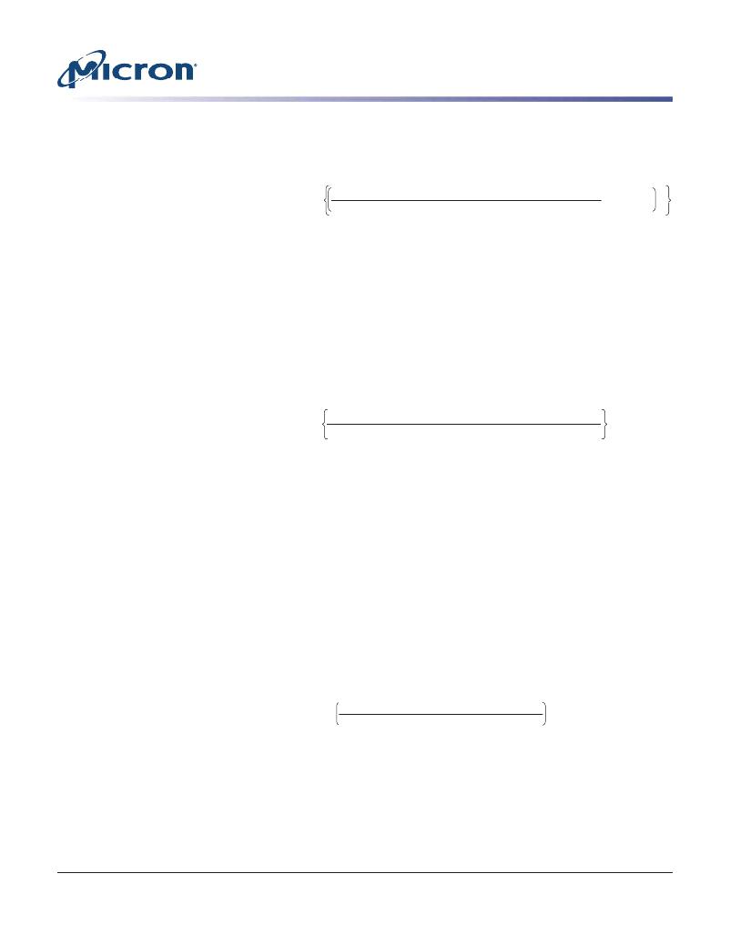
�CycleTimeDerating� =� max� PARAM� +� ERR(� nPARAM),act� –� ERR(� nPARAM),allowed� –� tCK(avg)� ,� 0�
�ClockCycleDerating� =� RU� PARAM� +� ERR(� nPARAM),act� –� ERR(� nPARAM),allowed� –� tnPARAM�
�ters.�
�t� t� t� t� t�
�tnPARAM�
�Cycle� time� derating� analysis� should� be� conducted� for� each� core� timing� parameter.� The�
�amount� of� cycle� time� derating� required� is� the� maximum� of� the� cycle� time� deratings� de-�
�termined� for� each� individual� core� timing� parameter.�
�Clock� Cycle� Derating� for� Core� Timing� Parameters�
�For� each� core� timing� parameter� and� a� given� number� of� clocks� (� t� n� PARAM),� clock� cycle�
�derating� should� be� specified� with� t� JIT(per).�
�For� a� given� number� of� clocks� (� t� n� PARAM),� when� t� CK(avg)� plus� (� t� ERR(� t� n� PARAM),act)� ex-�
�ceed� the� supported� cumulative� t� ERR(� t� n� PARAM),allowed,� derating� is� required.� If� the�
�equation� below� results� in� a� positive� value� for� a� core� timing� parameter� (� t� CORE),� the� re-�
�quired� clock� cycle� derating� will� be� that� positive� value� (in� clocks).�
�t� t� t� t� t�
�tCK(avg)�
�Cycle-time� derating� analysis� should� be� conducted� for� each� core� timing� parameter.�
�Clock� Jitter� Effects� on� Command/Address� Timing� Parameters�
�Command/address� timing� parameters� (� t� IS,� t� IH,� t� ISCKE,� t� IHCKE,� t� ISb,� t� IHb,� t� ISCKEb,�
�t� IHCKEb)� are� measured� from� a� command/address� signal� (CKE,� CS,� or� CA[9:0])� transi-�
�tion� edge� to� its� respective� clock� signal� (CK/CK#)� crossing.� The� specification� values� are�
�not� affected� by� the� t� JIT(per)� applied,� because� the� setup� and� hold� times� are� relative� to�
�the� clock� signal� crossing� that� latches� the� command/address.� Regardless� of� clock� jitter�
�values,� these� values� must� be� met.�
�Clock� Jitter� Effects� on� READ� Timing� Parameters�
�t� RPRE�
�When� the� device� is� operated� with� input� clock� jitter,� t� RPRE� must� be� derated� by� the�
�t� JIT(per),act,max� of� the� input� clock� that� exceeds� t� JIT(per),allowed,max.� Output� derat-�
�ings� are� relative� to� the� input� clock:�
�tRPRE(min,derated)� =� 0.9� –� tJIT(per),act,max – tJIT(per),allowed,max�
�tCK(avg)�
�For� example,� if� the� measured� jitter� into� a� LPDDR2-800� device� has� t� CK(avg)� =� 2500ps,�
�t� JIT(per),act,min�
�=� –172ps,� and� t� JIT(per),act,max� =� +193ps,� then� t� RPRE,min,derated� =�
�0.9� -� (� t� JIT(per),act,max� -� t� JIT(per),allowed,max)/� t� CK(avg)� =� 0.9� -� (193� -� 100)/2500� =�
�0.8628� t� CK(avg).�
�PDF:� 09005aef83f3f2eb�
�2gb_mobile_lpddr2_s4_g69a.pdf� –� Rev.� N� 3/12� EN�
�139�
�Micron� Technology,� Inc.� reserves� the� right� to� change� products� or� specifications� without� notice.�
�2010� Micron� Technology,� Inc.� All� rights� reserved.�
�发布紧急采购,3分钟左右您将得到回复。
相关PDF资料
MT45W1MW16BDGB-708 AT
IC PSRAM 16MBIT 104MHZ 54VFBGA
MT48H32M16LFB4-75B IT:C
IC SDRAM 512MB 54VFBGA
MT48H8M16LFB4-75 IT:K TR
IC SDRAM 128MBIT 133MHZ 54VFBGA
MTC100-JA2-P34
CONTACT INSERT PIN
MX841BE
IC CONVERTER WHITE LED 8-SOIC
MXHV9910BTR
IC LED DRIVER HIGH BRIGHT 8-SOIC
MXN12FB12F
MOTOR BRUSHED DC 12V 2922RPM
MXN13FB08B1
MOTOR BRUSHED DC 8V 4714RPM
相关代理商/技术参数
MT42L256M32D4KP-MS
制造商:Micron Technology Inc 功能描述:256MX32 LPDDR2 PLASTIC IND TEMP GREEN WFBGA 1.2V - Bulk